 It was one of those things that had been on my “Things I really want to do myself someday” list for a long time. I had seen it being explained by Per-Ivar in detail (in English and in Dutch) and the crazy Christmas card in 2017 that Per-Ivar and Arjan made in 2017 is legendary as far as I’m concerned (crazy in a good way as in “who comes up with the idea to create 50 of these and actually does it?!).
Per-Ivar had been so kind to send me a sticker to try myself. I still have it because I didn’t want to use it up and instead used it to show people the concept. Testing copper tape for paper circuits was something that I had already tried, together with the kids. But I decided that it was finally time to try to create electronic copper circuit stickers myself.
This post is nog going to be a step-by-step tutorial to follow along, but I will explain the process and link to the resources that I used during the process. Adding on to the information already out there.
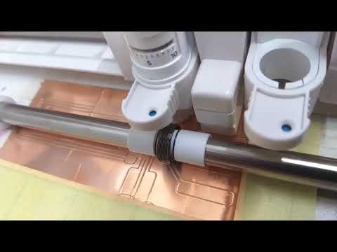
 Two tips before you try it yourself: #1 get to know your vinyl cutter and the software that goes with it before you try copper tape. You will need to figure out the pressure, knife settings, speed etc. for the copper. You need to be comfortable weeding delicate materials. It helps to know the ins and outs of the software so you can make the needed adjustments, test the settings etc.
Tip #2: go for slow, not too much pressure, make it cut twice.
Figure out the correct cut settings
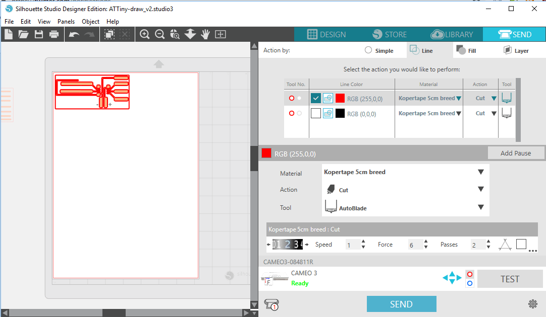
If all you wanted to get from this post are the settings in Silhouette Studio, see the image on the right:
Blade: 2; Speed: 1; Force: 6; Passes: 2; Overcut: No; Track Enhancing: No
You can find setting like this by making a small design, like a box with the intended line width and then cut it out and try to weed it. Was the cut too deep (and did you go through the backing?), not deep enough (then it won’t weed), depending on the result, change the cut force of blade depth, move the box to an uncut part of the tape and try again. This can be a long process. Make sure you save the settings as a new material type for later use.
I noticed that with difficult material, getting the speed down and instead make multiple passes improves the chance of succes. Unlike what I saw Arjan do, it did use the cut mat *and* some tape to keep the copper in place.
Design and cut the circuit
OK, now lets get going with the actual design. First, we need something to cut. Starting point for me was the PDF provided as part of the Christmas Card explanation.
 It can be opened in the free Inkscape drawing tool. I used that to do some measurements of the size and distance of the parts of the design. Now, I’m not as proficient in Inkscape as I would like, which resulted in me using Silhouette Studio for all the modifications. Because I had been working with Studio enough to know how to disassemble parts of the design, multiply, merge (weld) etc. And I paid for the Community version of Silhouette Studio, so I can import PDF and SVG directly.
Whether that is wise, is still up for debate. If you would like to share your designs with a broad community, you want something like SVG to share them in. From Inkscape, you can do a direct export to .SVG and make the file useful to anyone with a vinyl cutter. With Silhouette Studio, you’re limited to .studio files if you’re using the Free of Community edition (the Business edition allows for SVG export) unless you use online tools like this converter site that allows 10 free conversions per day. Now the site I’m linking to did work without a problem on the two designs I “created” (modified from the originals), but it is choice you’ll have to make.
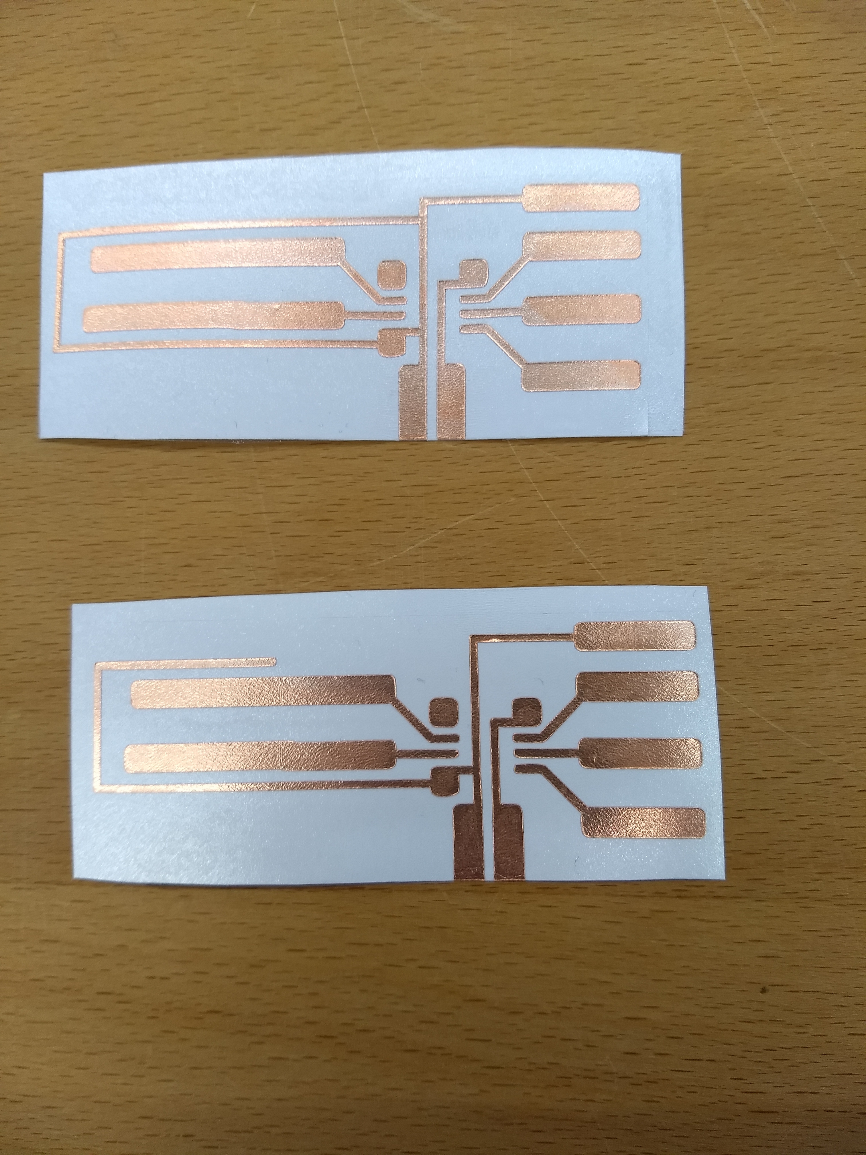
The SVG files for the two desings can be downloaded here: SVG files (ZIP)
 Personally, I really like the option in Silhouette Studio to cut and weld vector shapes. After welding I would still have a vector, making it really easy to re-use parts of the design by Per-Ivar. See the gif on the right for an example where I use it to resize a part of a circuit.
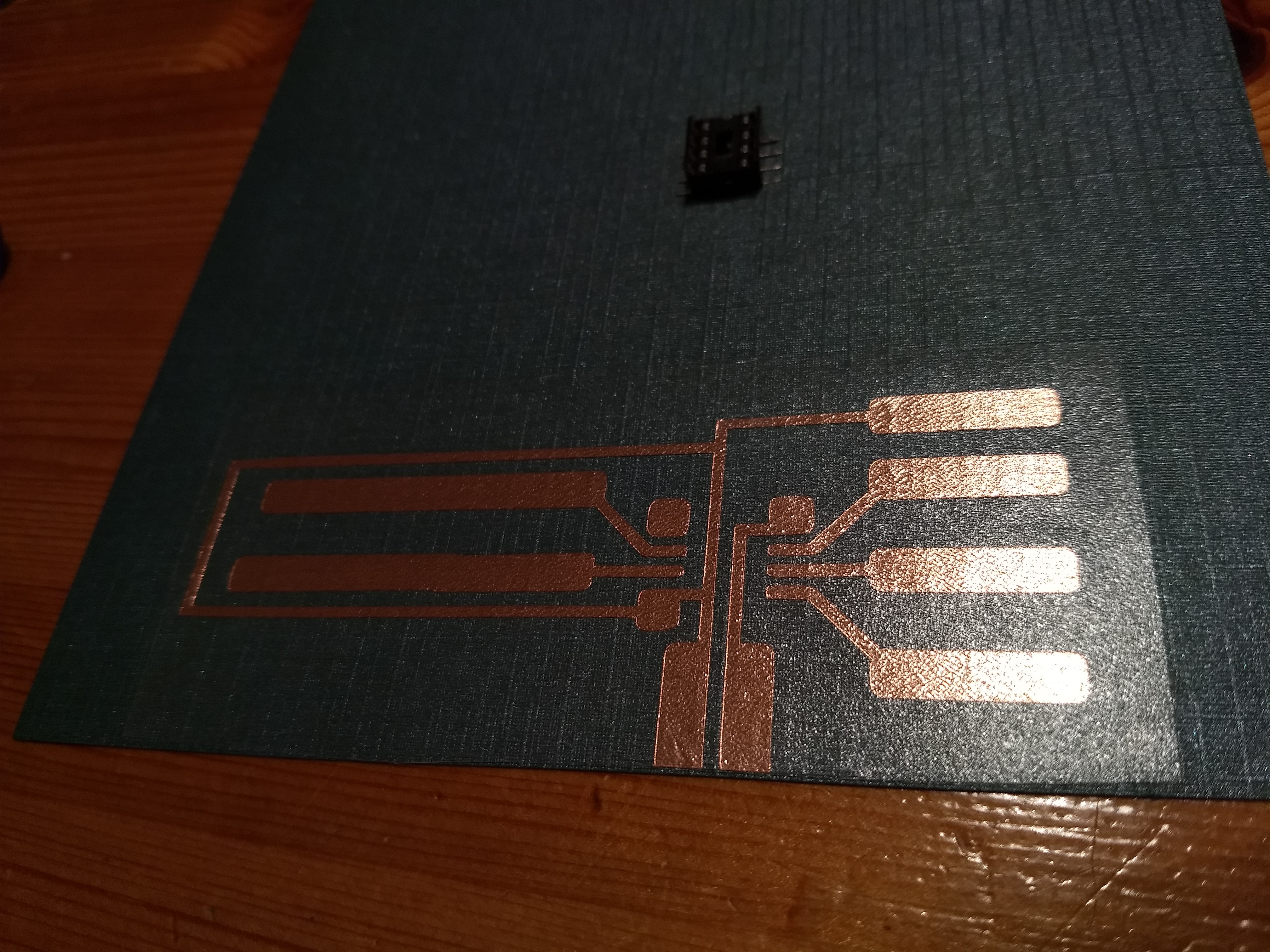
One thing that I made sure I didn’t modify was the layout of the pins for the ATtiny85. Something I did have to modify was the height of the layout. Per-Ivar used a roll of 10 cm wide copper tape. The tape I had at the moment is only 5 cm wide. So, while the width of the design was only limited by the length of the tape (30 meters on the roll) or the width of the vinyl cutter (12 inches), I had to make some choices. I decided to remove the part that can be used to solder on the coin cell battery holder and modify the lower part of the design so that I could use alligator clips to power the circuit.
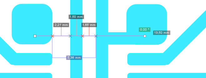
I drew a cut box with height of 5 cm around the design as an easy visual reference of the max height while designing.

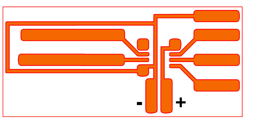
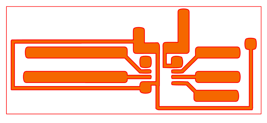
 I only now noticed that I flipped the original design (in blue on the left) upside down. Luckily I looked at the logic of the design so I knew which was the + and which was the ground (-) part of the design. The middle design is actually the second iteration of that design. The first one did not have the ground lines connecting (see image to the right). Now there is absolutely no reason for them to connect other than aesthetics (it looks better). But, hey, why spend all this time creating something if it looks bad, right?
The second design uses the pads for the the coin cell battery holder and leaves out the pads for the crocodile clips.
The choice of wide or smaller tracks is also partly preference. I learned afterwards, that given my bad soldering skills, the wide ones are much easier to solder on. But they use up much more, valuable space. For the two designs I choose to use the smaller ones for the ground tracks going back from the LEDs to the ATtiny85. That also made it easier to keep track of which was the ground.
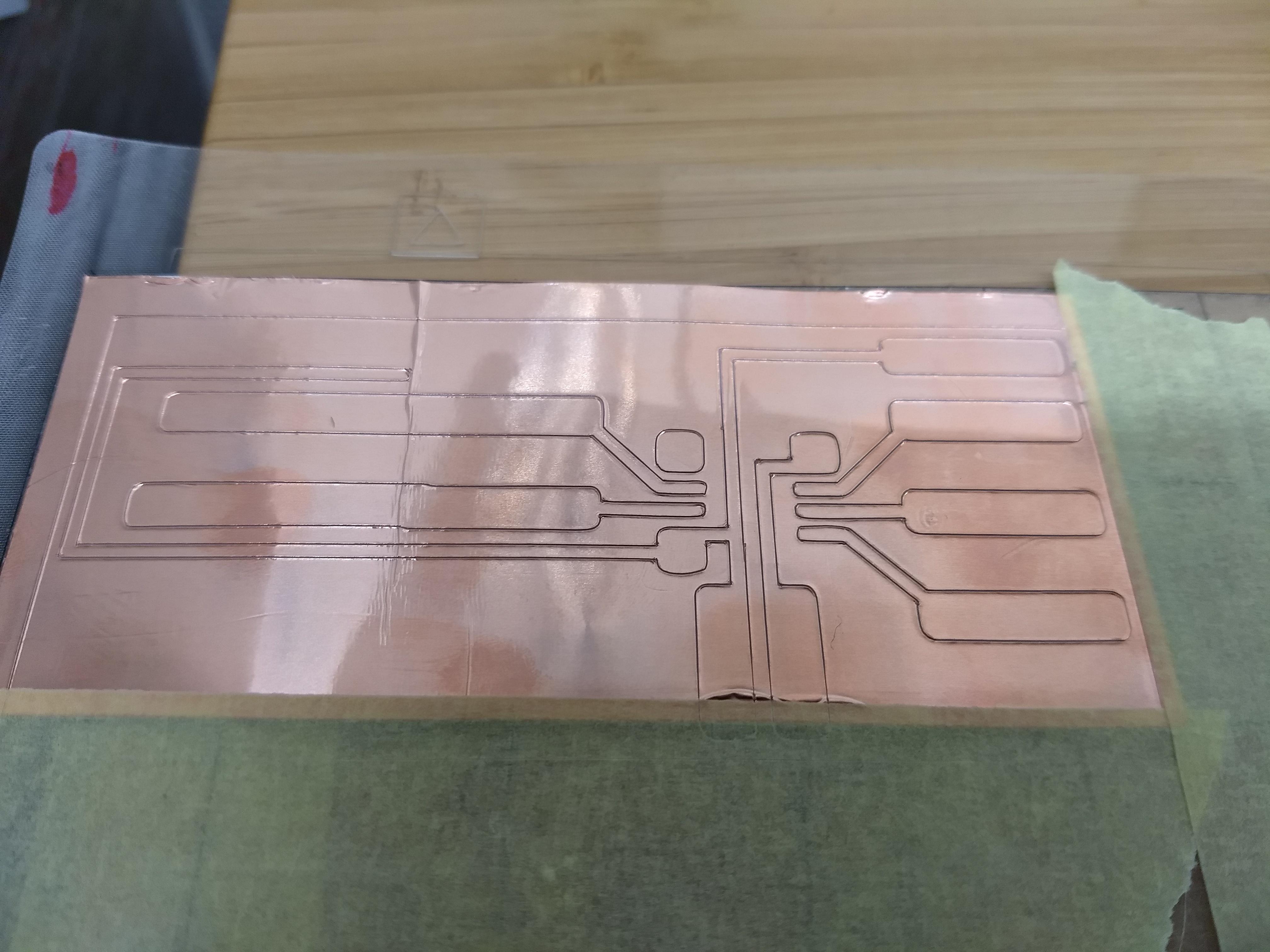
So, the vinyl cutter part of the work turned out to be surprisingly easy: figure out the correct setting (usually takes much longer than this time), design, cut, weed, put transfer tape on. Done.
Write the code
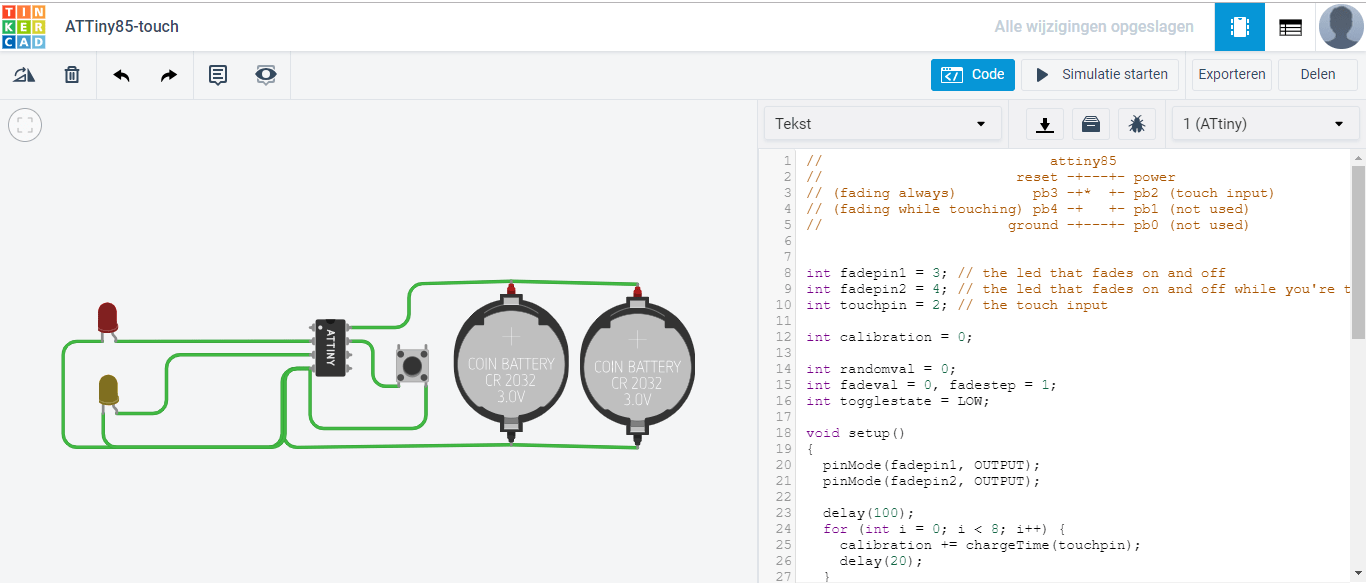 In the Christmas card example Per-Ivar and Arjan explained how they used Tinkercad to write and test/simulate the code they used for the circuit. Now, I have done a fair bit of Arduino programming, so Tinkercad and a block based environment would not have been my first choice. But I thought, let’s give it a go.
Nice about Tinkercad is that you can actually “build” the resulting circuit and then simulate the results in the online environment. I later did also do it the old fashioned way by using a breadboard and actual LEDs (forgot to take a picture). That test showed that Tinkercad probably assumes a 1Mhz setting for the ATtiny while I (by accident/default) used the 8Mhz setting in Arduino to program the ATtiny. The result was a much faster execution of the code and much faster blink frequency of the LEDs.
In the end, I did not use the block based part of Tinkercad. Because, unlike with the Christmas card, I wanted to add interaction to my design. I knew I had seen Per-Ivar use the capacitive touch functionality of the ATtiny85 in some video (couldn’t find it) so I started Googling for examples and found this code. Of course the code wasn’t usable just by copy-pasting. They had a different pin-layout and used more LEDs than I intended for the first design. I modified the code (removed what was not needed, added a variable for the touch-pin) and pasted into Tinkercad to test. It worked.
You can find the code I used online here on Github.
Programming the ATtiny85
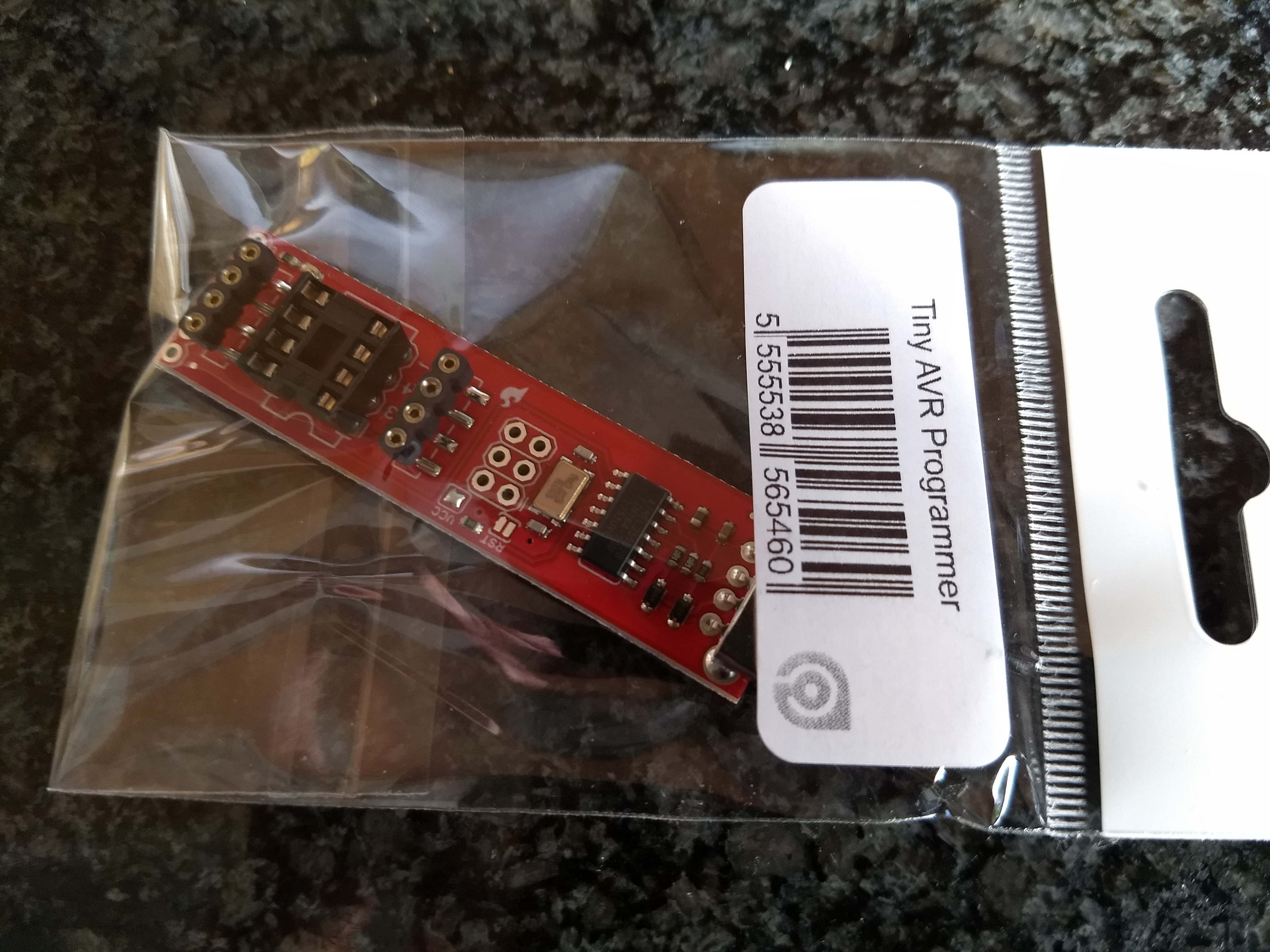 Before, I had been using the cheap “use an Arduino” (blogpost in Dutch) option to program an ATtiny85. Primarily because I thought 20+ euros just for a programmer was too much. But I caved and spend the money to buy an official SparkFun Tiny AVR Programmer. Because I had used the Arduino route before, all the drivers had been setup on my laptop already. If it is the first time you’re doing this, please read the extensive instructions here and on the SparkFun website.
With the programmer, programming and testing an ATtiny85 is as easy as using an Arduino.
Almost finished
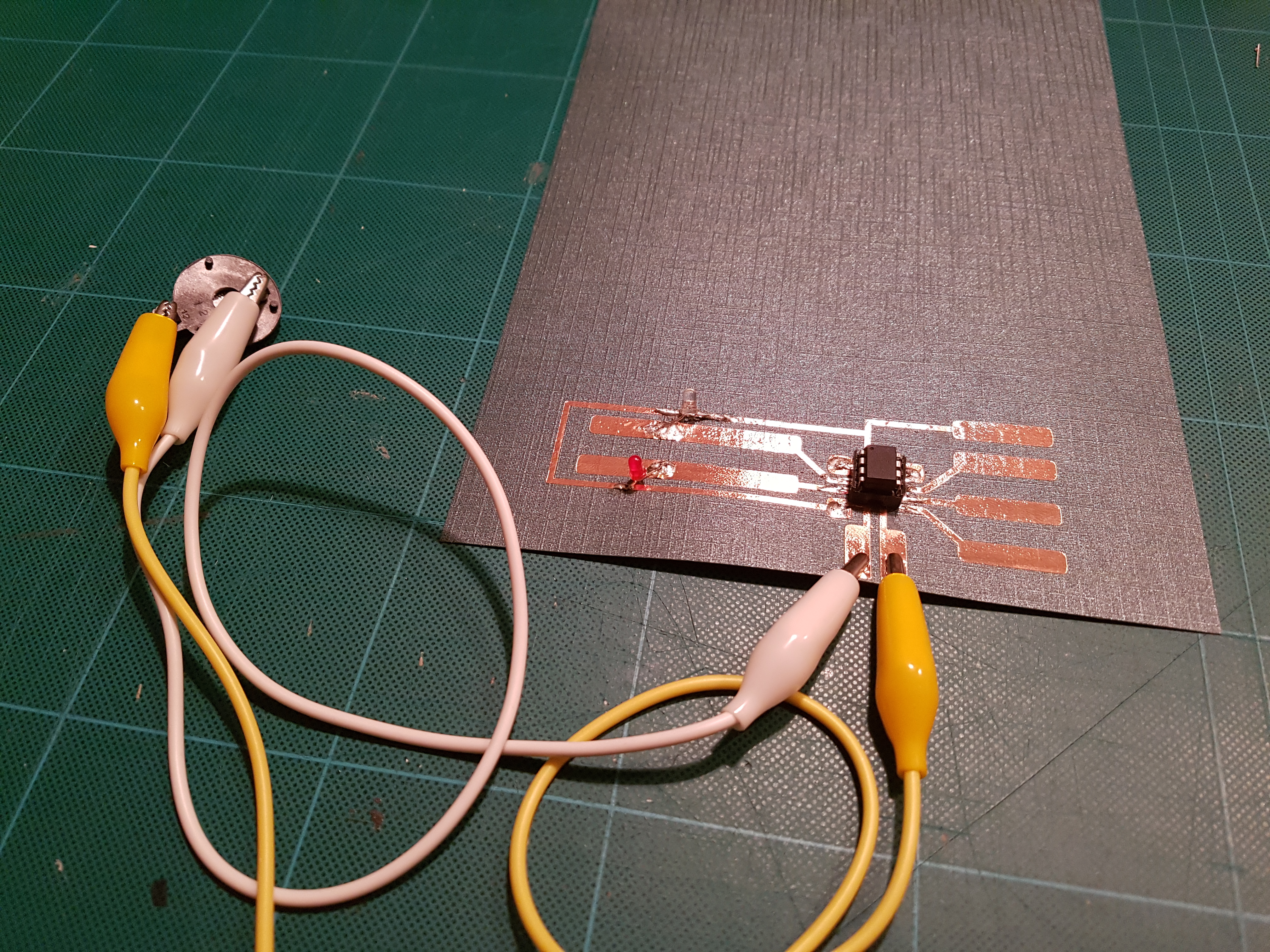
After uploading the code to the ATtiny85 and testing that it working using a breadboard, it was time to transfer the copper circuit to a carrier (thick paper in this case) and solder all the parts on it.
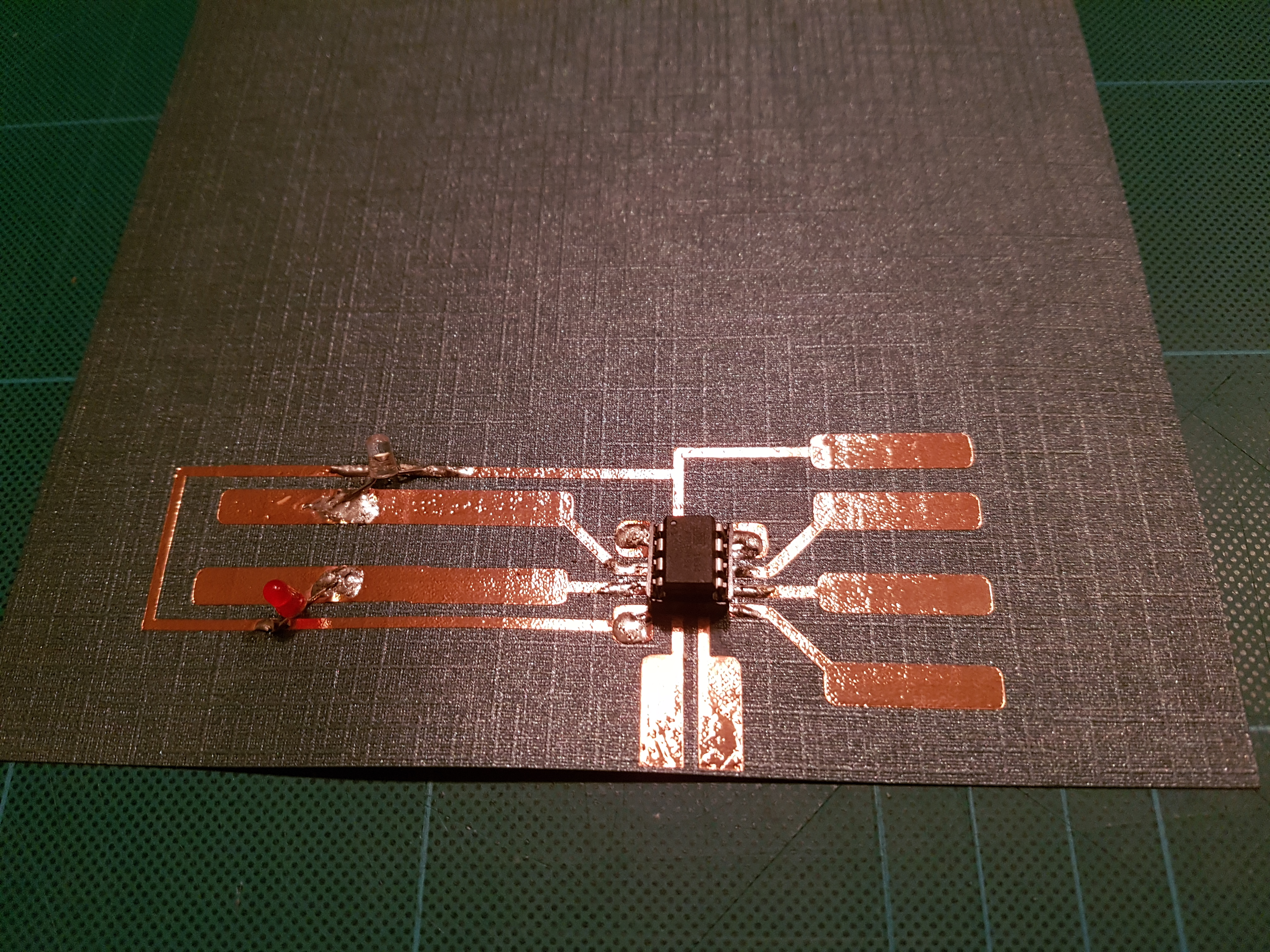
Soldering is not something that I’m really good at. Soldering on copper tape takes some getting used to. You’re not soldering through hole, it more resembles SMD soldering. So, my result would not get an A when judged purely on that aspect. But for me, the most important thing was, it works!!!

As you can see, I used regular LEDs with the legs cut off as short as possible. Next version will have SMD LEDs and probably cleaner soldering. The most important result personally is that I now know that I control the production process. Now it is only limited to what possible uses I can come up with. It could be simple circuits like this traffic light example, or … (ideas?)
Thanks for reading this really long post. I hope it helps you if you want to try it yourself. And of course a big thank you to all the people that provided all the information that I needed to get this to work!
 AI-tools")


