 Since some of the people that inspired this weekend project can’t read Dutch, I decided to do the follow up of part 1 / deel 1 in English. That first part, posted yesterday evening late showed work in progress. Today, the Panda Ballerina was completed. Before I show you the end result, I wanted to go into the steps involved in a bit more detail.
Like I mentioned, the Paper Panda Prototype by Jeannine Huffman was the initial inspiration. That project is already a year old, but I think it was Per-Ivar Kloen that tweeted about it recently. That combined with the tweet by Sarah Magner determined the theme: a Panda Ballerina.
Now both the Paper Panda and the Ballerina use copper tape / paper circuits, my order of tape is still on its way, so that wasn’t possible yet, but I did receive the ATtiny85 chips, although in a different form factor, in my case as a DigiSpark ATtiny85. We had some TowerPro SG90 servos and a couple of LEDs, so the idea was to create one using 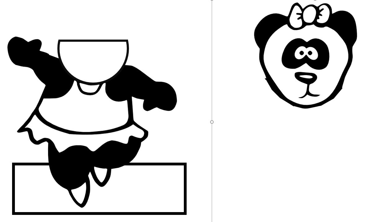 thin plywood.
Template
First step was to come up with a template. Now I have to admit, Googling one is no problem for a private setting, for say classroom use it is best to use one where you are more sure about the rights to re-use and make derivative works then I am for this one: I could not find the original creator. So, draw one yourself if you want to be 100% sure that it is OK. After you draw you figure, you have to separate the two parts. In my case I made a copy and using the lasso tool, I erased the body for one copy and the head for the other copy. Then I added something neutral looking that could act as a nek. For the next version that part is going to be smaller and less visible, but you need something to attach the servo to.
Print, transfer to plywood, cut the plywood with a jigsaw, carefully smooth with sandpaper and add color. We glued a second black/white version to the wood because that allowed the drilling of holes for the LEDs in the head without later seeing the actual LEDs.
Wiring scheme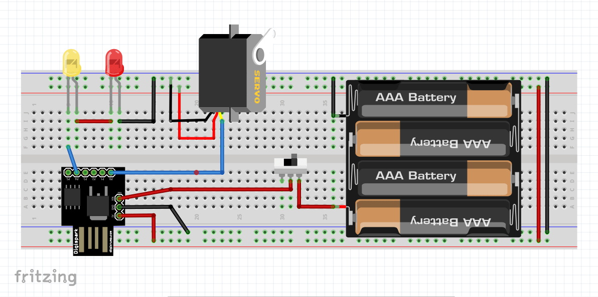
The wiring needed for the project in itself wasn’t that difficult. See the Fritzing sketch to the right. A Fritzing symbol for the DigiSpark ATtiny85 was available here, there probably is one for the TowerPro servo also, but there I did not mind as much as with the DigiSpark. A normal ATtiny85 (by default available in the library of Fritzing) only has 8 connections while here I also use the VIN connection for the battery pack power.
Getting it off the breadboard took some soldering, but not something that was too dramatic. I added the header pins to the DigiSpark and re-used some of my breadboard cables, soldering one end while retaining the pin on the other end to attach to the DigiSpark.
Coding
Coding the ATtiny85, even the Frtizing version is much less easy than a regular Arduino board. In particular the debugging is a bit more difficult without the serial prompt.
I started with the code provided on the Paper Circuits Resources page. That did not work. It took some debugging to decide that it probably was a problem of the code in combination with the library. The regular Arduino “servo” library did not work either.
In the end, this one worked. I started with a simple code that only moved the servo, then added the LED code.
After everything worked I added some randomization. The delay between movement and the total angle of the head movement are not always identical.
The code is available hier.
Putting it all together
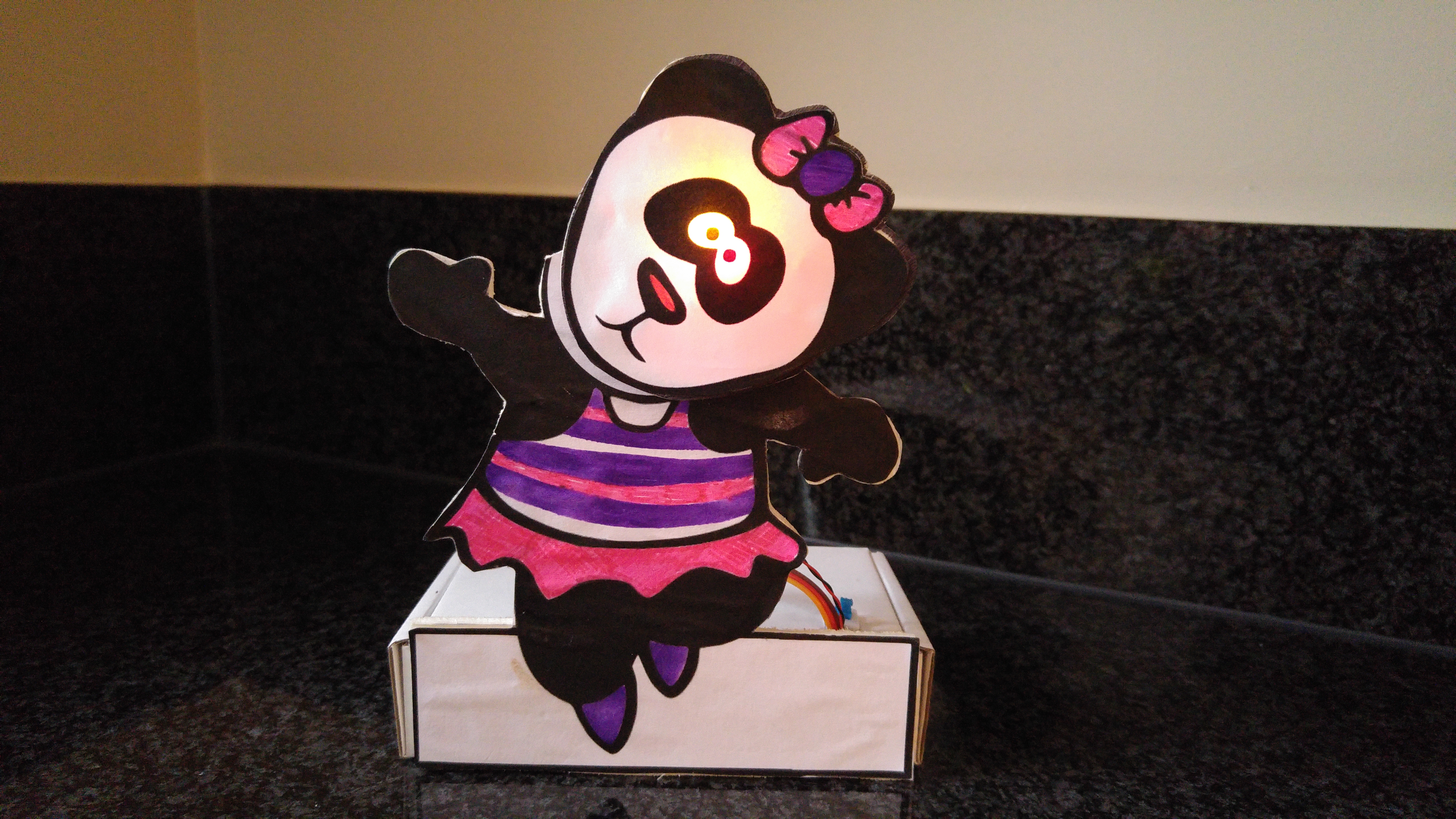
A small cardboard box was re-used to contain the battery box, the DigiSpark and the access cables. We used extra thin wire for the connection with the LEDs so that it would not be a problem when the head was moving. An On/Off switch in the top of the box made sure that it was easy to switch it off when needed and conserve the batteries. After some testing and tweaking of the angles and speeds of the head movement, the paper face was attached over the LEDs.
This is the end result:


